In the last few months, I got into antennas a little bit deeper.
The pursuit of the best antenna for my location took me to interesting places.
My magnetic loop project is on hold right now, as it became too big and would attract attention when placed on the balcony.
I definitely need to finish the series and I will do it sooner or later.
This time, I got a recommendation for a base-loaded vertical antenna.
After receiving an MFJ coil-loaded vertical antenna (not sure, but the model might be MFJ-1622) for testing I decided to give it a try.
Calculations, of course.
Shortened vertical antennas have a coil to electrically fill the gap of shorting the radiating element.
The first thought was to copy the design of the MFJ antenna with some minor changes but then I decided to go on a different path and design it almost from scratch.
Using this calculator: https://m0ukd.com/calculators/loaded-quarter-wave-antenna-inductance-calculator/
I got the inductance needed for the coil.
The frequency was meant to be 14 MHz but I decided to go with the lowest frequency that I want which is 7 MHz.
These are the parameters I’ve used: Frequency: 7 MHz Length of vertical or dipole element: 1.5M Coil position (Distance from feedpoint): 0 Wire diameter: 1.5mm (electrical wire)
The result was around 40uH.
Calculating the coil
You may ask yourself, how do I know how to make the coil close to 40uH?
Good question!
You use another calculator.
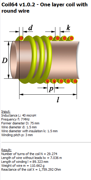
This time I’ve used Coil32 calculator, which is awesome! (thanks to Valery Kustarev for making it)
You can download it here: https://coil32.net/download-coil64-for-windows.html
Coil calculators can be found online but they don’t take into account the calculations for the spacing between the windings which is important when you design a coil with adjustable inductance.
When the spacing of the coil increases, the inductance decreases.
The parameters used for my coil
Designing the coil
For this coil I decided to use 75mm PVC pipe to keep the coil short.
Taking a PVC pipe and wrapping wire around it isn’t easy, especially when the spacing between each turn needs to be maintained.
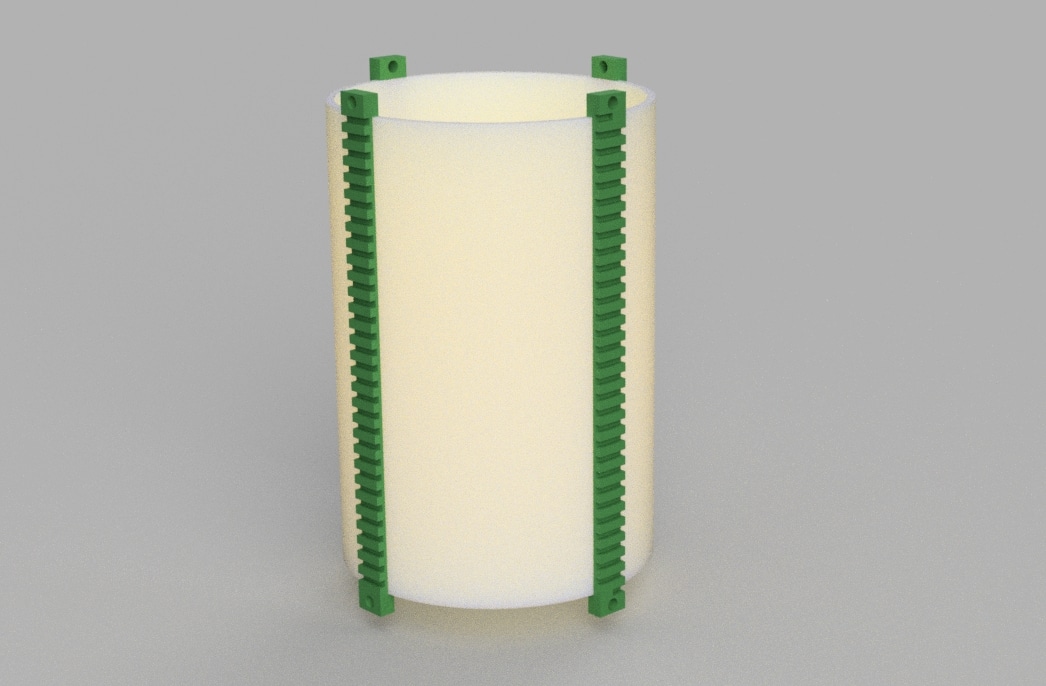
So I decided to 3D print stripes to hold the wire.
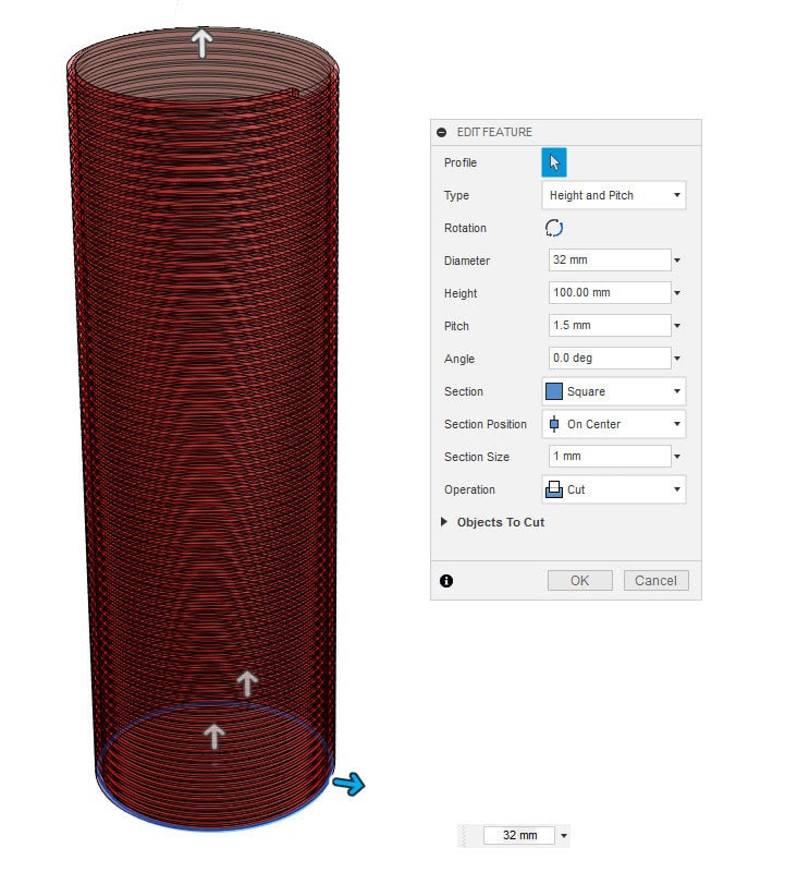
For this step I used Fusion360 and created a model of the PVC and 4 support stripes.
Using the coil function of the software I entered the parameters from the calculator (and added tolerances).
Example of the coil function of Fusion360
Quick render of the coil stripes
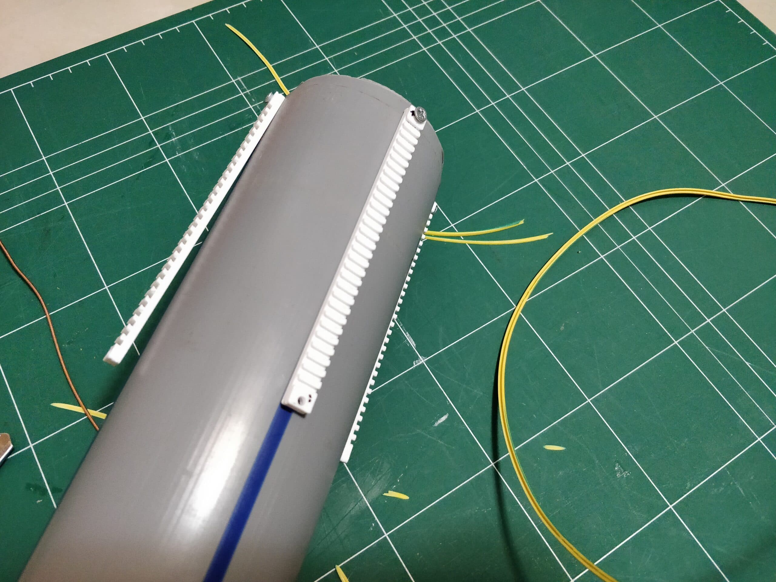
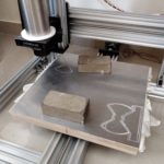
Printing and Assembling
After printing the stripes I used screws to hold it in place
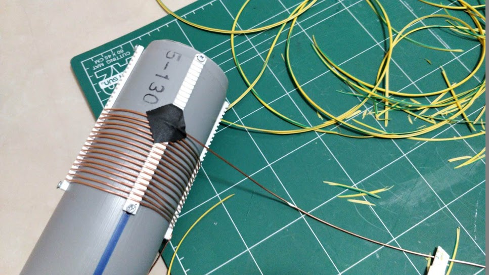
With a little knife I took off the insulation of the wire and started winding.
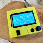
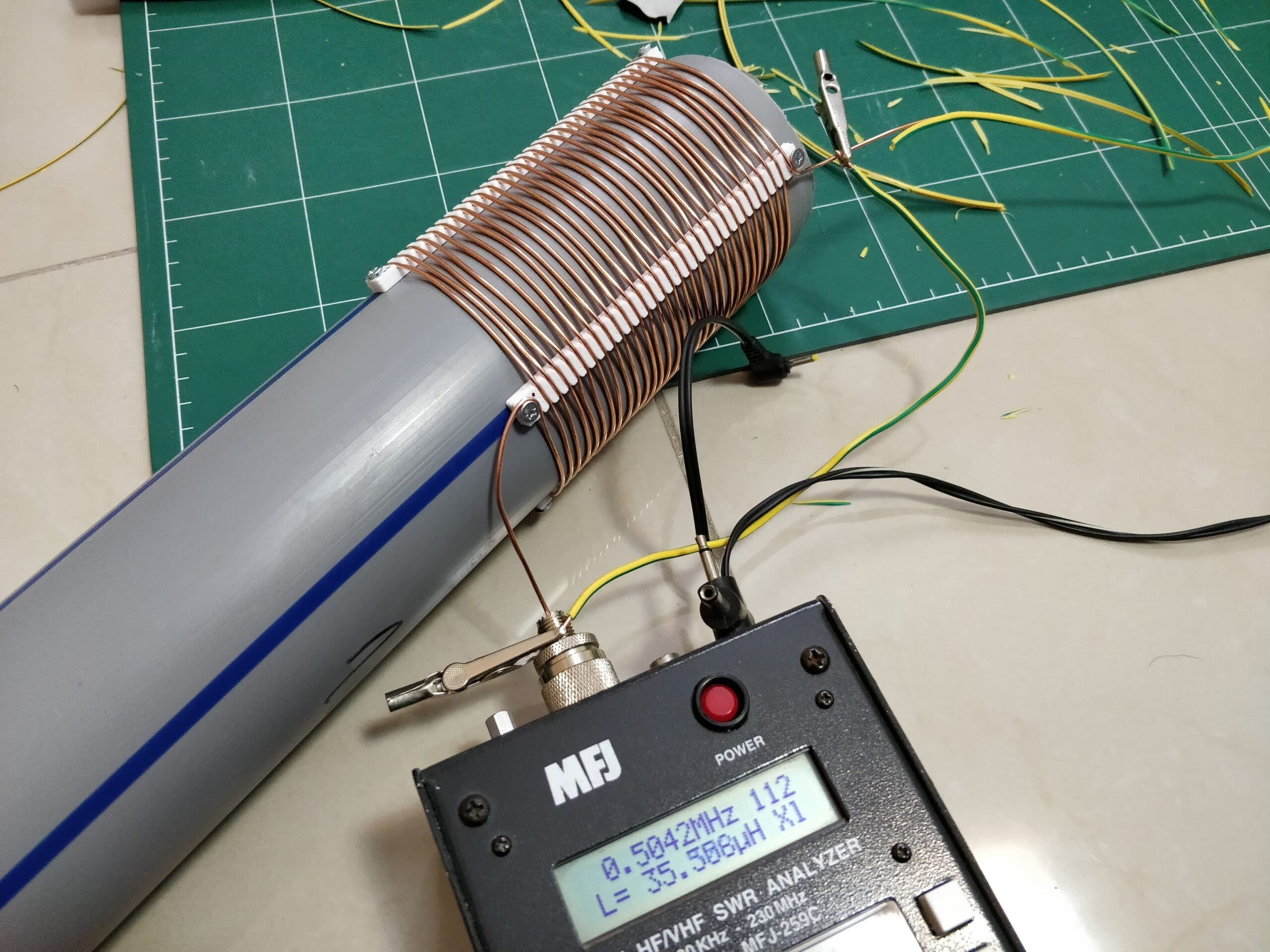
When finished I did some testings to see if I got the right inductance.
Hmm, close enough.
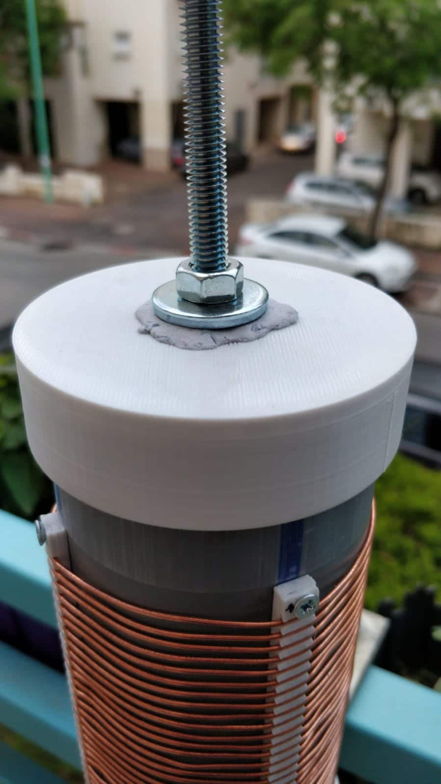
Caps
Unfortunately I couldn’t find any caps for 75mm PVC so I had to design and print by myself.
The top cap was a little bit weak so I got some plastic epoxy to reinforce it and then drilled the hole again.
For the bottom cap I designed a better and thicker version
Both caps are held by pressure with a tight fit (although I made some holes to put screws in the bottom).
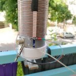
The bottom cap has a 20mm screw that connected to the mount (made out of metal by a friend, thank you Mark).
After few days in the sun, the top cap started to warp and the whip inclined more and more.
I used a metal can to give it a little bit more strength and pushed the cap inside.
An electrical tape was used to avoid contact between the can and the whip.
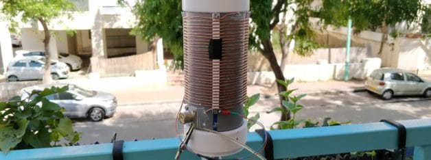
The coil
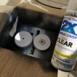
Coating the caps for UV
The whip
At first, I wanted to use a telescopic antenna like MFJ had but ordering it from eBay would take too much time.
Thus, 6mm threaded rods were chosen but none found on the hardware store so 8mm was the size to go.
I bought 2 x 8mm rods (length 1m each) with long threaded nut to connect them together.
In the end, it wasn’t stable enough so I used only 1 meter and it worked fine.
In order to reduce the weight on the cap, metal bar was cut off a fence and welded together with screw.
Got 2 pieces, 1m and 1.5m so far only used the 1m (thanks again Mark!).
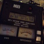
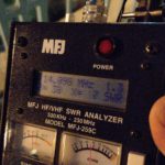
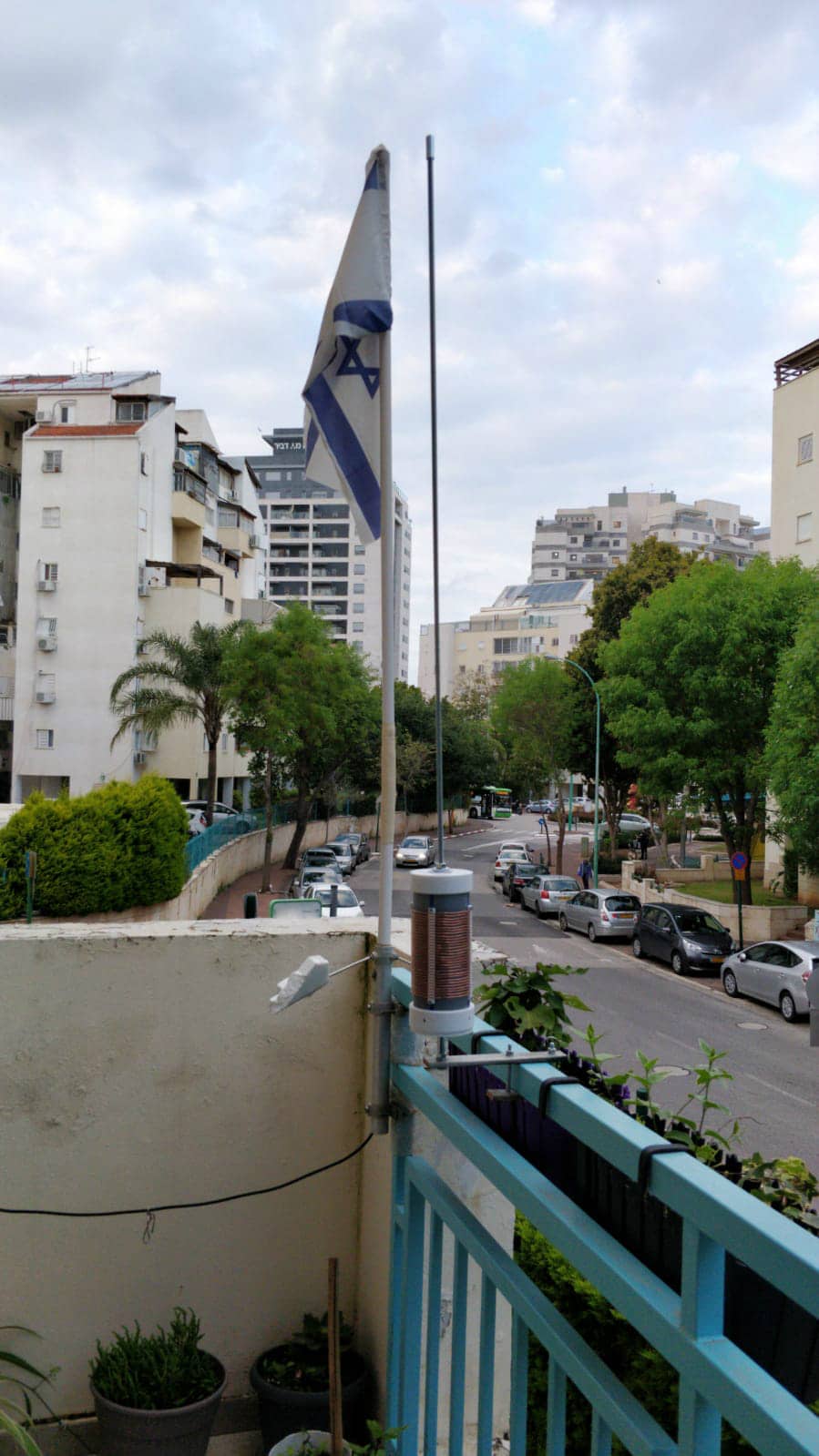
Testing
I could not resist testing it so the pictures were taken in the night, sorry about the quality.
Finding the spot for 20m band was easy.
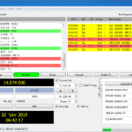
The first test on the radio was awful, and I blame the conditions (and the fact that it was night time).
On the next day I got pretty good results.
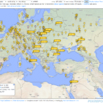
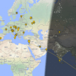
TX test, was good into Europe
First QSO on FT8
Received some stations from India and Indonesia
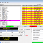
Next test was done on 17m band and it was amazing.
Even in the US
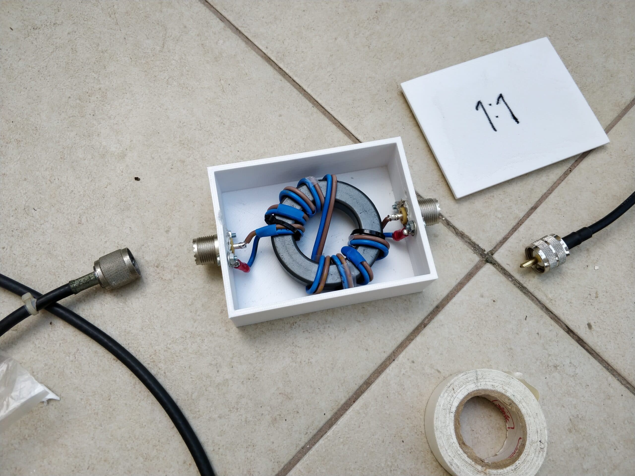
Choke and Counterpoise
Counterpoise length made of 6m of wire.
In order to eliminate RFI, I made 1:1 current mode choke as shown here: https://www.youtube.com/watch?v=9kY2rz2jizs
Mine was made out of Fair-Rite43 because that’s what I had in that moment.
That solved most of the RFI issues but I couldn’t get good SWR with both the choke and counterpoise so I took the wire off. Fair-Rite FT240-43 on eBay
That’s it.
This project was very interesting and I’m happy with the results so far.
73!
UPDATE: I replaced the whip with telescopic antenna due to melting of the plastic cap (one hot day with 40 degrees celsius).
It weighs 65g and extends up to 1.2m (the seller declared 1.5m but it was misleading and he refunded me).
Works as well as the threaded rod. Telescopic antenna on eBay
We use cookies on our website to give you the most relevant experience by remembering your preferences and repeat visits. By clicking “Accept All”, you consent to the use of ALL the cookies. However, you may visit "Cookie Settings" to provide a controlled consent.
This website uses cookies to improve your experience while you navigate through the website. Out of these, the cookies that are categorized as necessary are stored on your browser as they are essential for the working of basic functionalities of the website. We also use third-party cookies that help us analyze and understand how you use this website. These cookies will be stored in your browser only with your consent. You also have the option to opt-out of these cookies. But opting out of some of these cookies may affect your browsing experience.
Necessary cookies are absolutely essential for the website to function properly. These cookies ensure basic functionalities and security features of the website, anonymously.
Cookie
Duration
Description
cookielawinfo-checkbox-analytics
11 months
This cookie is set by GDPR Cookie Consent plugin. The cookie is used to store the user consent for the cookies in the category "Analytics".
cookielawinfo-checkbox-functional
11 months
The cookie is set by GDPR cookie consent to record the user consent for the cookies in the category "Functional".
cookielawinfo-checkbox-necessary
11 months
This cookie is set by GDPR Cookie Consent plugin. The cookies is used to store the user consent for the cookies in the category "Necessary".
cookielawinfo-checkbox-others
11 months
This cookie is set by GDPR Cookie Consent plugin. The cookie is used to store the user consent for the cookies in the category "Other.
cookielawinfo-checkbox-performance
11 months
This cookie is set by GDPR Cookie Consent plugin. The cookie is used to store the user consent for the cookies in the category "Performance".
viewed_cookie_policy
11 months
The cookie is set by the GDPR Cookie Consent plugin and is used to store whether or not user has consented to the use of cookies. It does not store any personal data.
Functional cookies help to perform certain functionalities like sharing the content of the website on social media platforms, collect feedbacks, and other third-party features.
Performance cookies are used to understand and analyze the key performance indexes of the website which helps in delivering a better user experience for the visitors.
Analytical cookies are used to understand how visitors interact with the website. These cookies help provide information on metrics the number of visitors, bounce rate, traffic source, etc.
Advertisement cookies are used to provide visitors with relevant ads and marketing campaigns. These cookies track visitors across websites and collect information to provide customized ads.


 DIY Shortened Vertical Antenna
 Controlling Somfy blinds with ESP8266
 AllStar to DMR bridge
 Repeaters Frequency Calculator
 Accessing LAN over ZeroTier easily
 Using The QYT KT8900 for an Allstar node
 Building APRS Digipeater with Raspberry Pi
 DIY Magnetic Loop – Part 1 – The Capacitor
 AllStar Node using the Baofeng 888
 Callsigns instead of node numbers on Allstar