Keeping a PC powered on with an Arduino Some background... I needed an option to…
SSD1306 OLED Screen
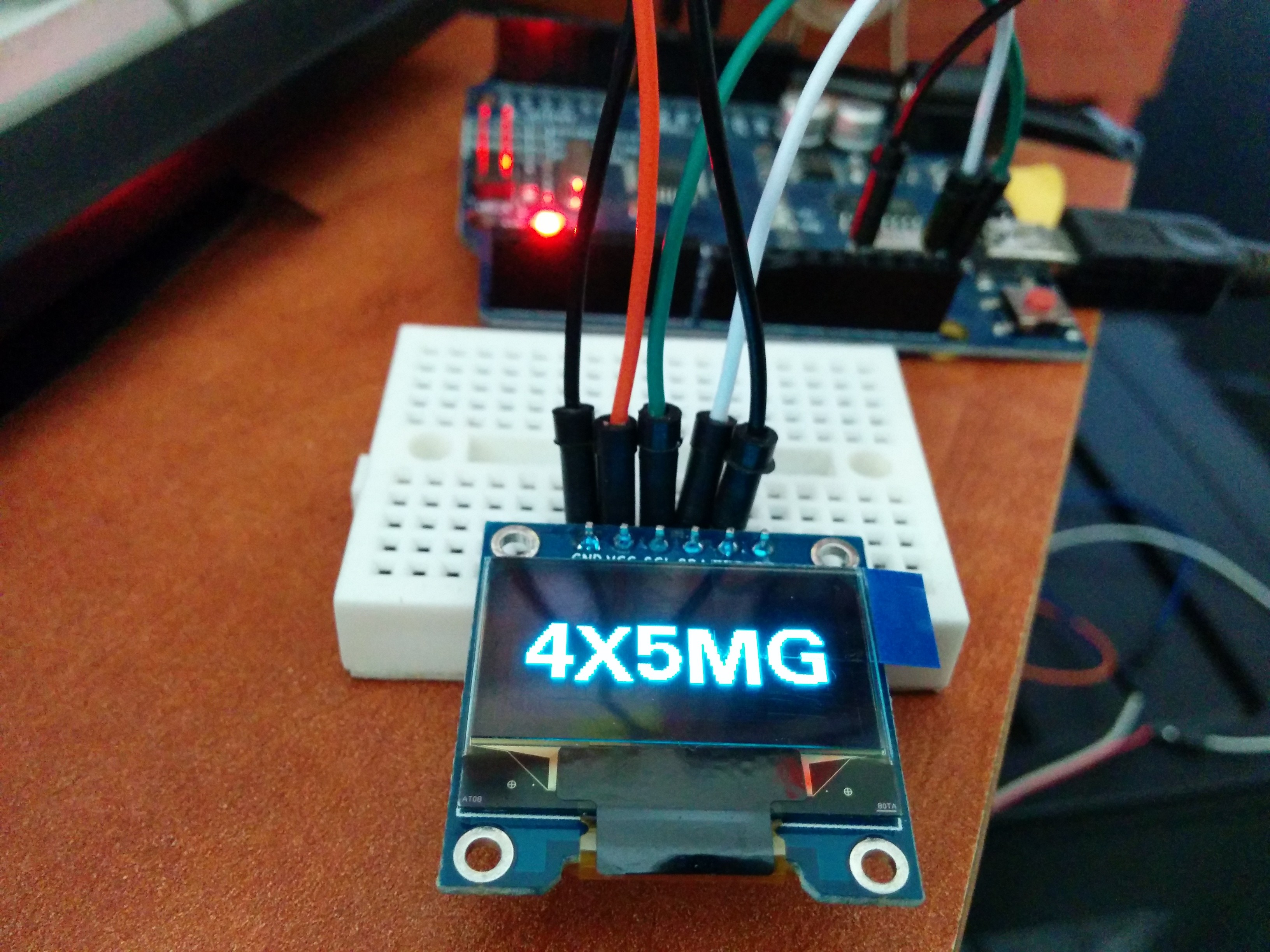
The Screen
SSD1306
I recently purchased a small screen for a project I want to build.
The screen is 0.96” OLED SSD1306 from eBay.
I want to build a small clock based on the DCF77 module (I hope it’ll work here) and DHT22 sensor for temperature and humidity.
SPI or I²C?
I struggled for hours to set this screen up, I found that I can use either SPI or I²C (I2C, IIC).
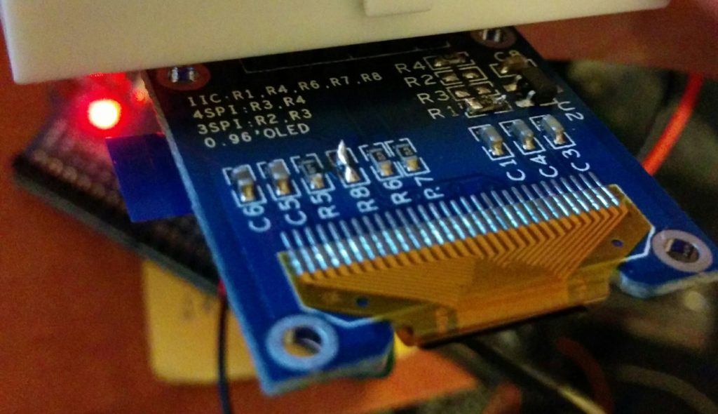
It came on SPI mode and I wanted to use the I2C so I had to rework the PCB and move the R3 resistor to R1 and solder the two pads of R8 together.
Before (as SPI mode):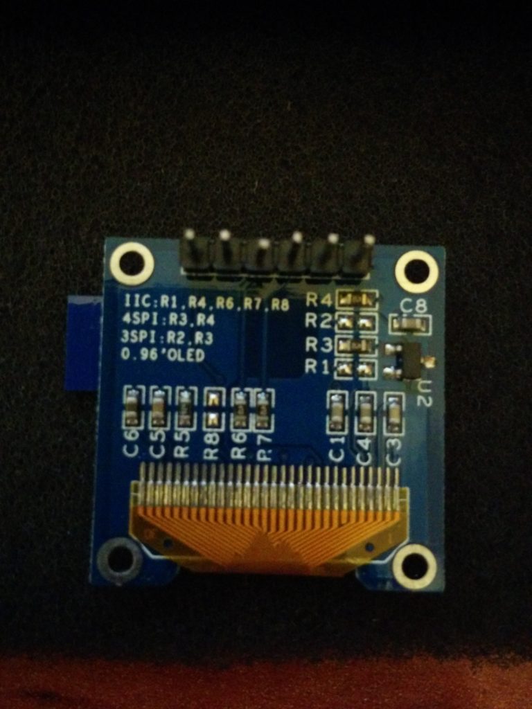 And after (as I2C mode):
Libraries
I used both the Adafruit SSD1306 and U8GLIB successfully.
Adafruit SPI
For Adafruit as SPI I used “ssd1306_128x64_spi” example.
U8GLIB SPI
For U8GLIB as SPI I used the “Hello World” example and used this constructor:
U8GLIB_SSD1306_128X64 u8g(10, 9, 12, 11, 13); // SW SPI Com: SCK = 10, MOSI = 9, CS = 12, A0 = 11, RST = 13
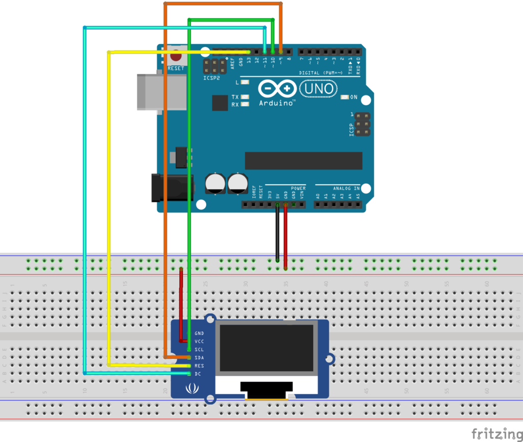
The wiring:
OLED — Arduino Uno
GND — GND
VCC — 3.3V (Or 5V, depends on the OLED)
SCL — Pin10
SDA — Pin9
RES — Pin13
DC — Pin11
Adafruit I2C
For Adafruit as I2C I used the “ssd1306_128x64_i2c” example and changed the address to 0x3c instead of 0x3D.
U8GLIB I2C
For U8GLIB as I2C I also used the “Hello World” example and changed the constructor to:
U8GLIB_SSD1306_128X64 u8g(U8G_I2C_OPT_DEV_0|U8G_I2C_OPT_NO_ACK|U8G_I2C_OPT_FAST); // Fast I2C / TWI
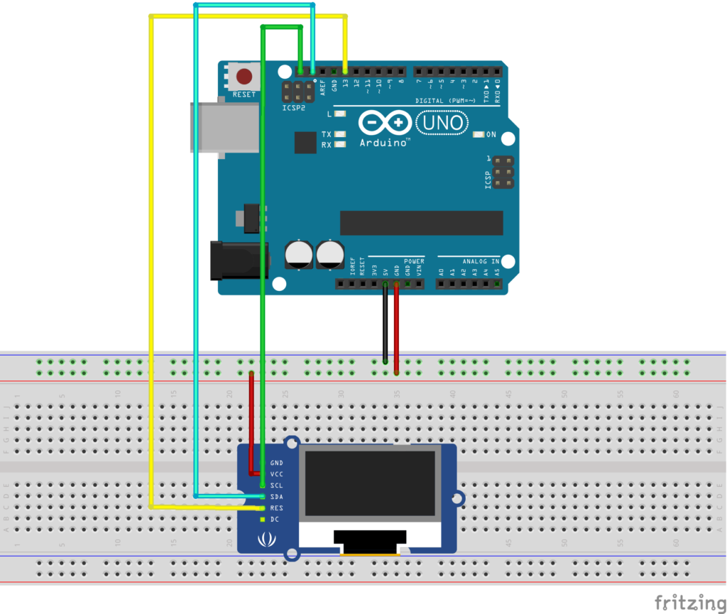
And the wiring:
OLED — Arduino Uno
GND — GND
VCC — 5V (Check you screen specs)
SCL — SCL
SDA — SDA
RES — Pin 13
To change the address, connect DC to Pin 12 (should work)
That’s it.
I hope I helped a bit with this information.
Good luck!
