Building APRS Digipeater with Raspberry Pi
Intro
I had this idea for a long time, building digipeater for the APRS network that will be both cheap and easy to build.
Some research was done but the project paused because I didn’t have time and I wasn’t really sure how to connect a radio to the system.
Few days ago someone gave me a chinese radio called FDC FD-150A (along with some Motorola and Kenwood handheld radios that will be used in other projects) and I decided to get back to the table and build it.
Later, I wanted to try with Motorola Maxtrac and it worked as well.
Hardware and Software
What do we need?
- Raspberry Pi 3
- MicroSD card loaded with Raspbian
- USB Soundcard (I used CM108 chip)
- Radio
- Some wires
Raspberry Pi 3 On eBay
16GB MicroSD card on eBay
USB Soundcard on eBay
For the software side we will use DireWolf.
The Build
First download Raspbian from here.
I chose the Stretch lite version but if you want to use Xastir (APRS client with map) got for the GUI version.
Then flash it on the MicroSD card with you favorite software.
Win32DiskImager will do the job but I used Etcher this time.
If you’re using the lite version or you need SSH out of the box you might need to place blank file called SSH under the boot drive.
Load the card in the Pi and power it on.
If you’re using the GUI version you can configure whatever you want like VNC etc.
Now, find your Pi’s IP and SSH to it.
After logging in get the latest update by typing:
sudo apt-get update
sudo apt-get dist-upgrade

sudo rpi-update (UPDATE July 2020: RPi foundation doesn't recommend using this command)
sudo reboot
When it’s all done enter:
dpkg-query -l 'pulseaudio*'
This will check if PulseAudio is installed.
I did this procedure few times and never had it installed (maybe on the GUI version it’s built in?)
So you’ll need to remove it by typing:
sudo apt-get remove --purge pulseaudio
sudo apt-get autoremove
rm -rf /home/pi/.pulse

sudo reboot
Now we will install Direwolf:
cd

sudo apt-get install libasound2-dev

git clone https://www.github.com/wb2osz/direwolf
Now let’s compile it:
cd direwolf
makecd
sudo make install
make install-rpi

make install-conf
If you’re using the lite version you’ll get an error because the installation can’t copy the desktop shortcut as we don’t have desktop.
Let’s test the software first, just type direwolf and wait for it to load.
Direwolf should plot few lines including its version and few other things.
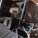
Connecting the radio
I opened the radio and found the RX audio from the potentiometer, TX audio from the headphones jack, PTT from the button and ground from any ground point.
This radio has Mic and Headphones jacks but I couldn’t fit two plugs together due to tight space so I had to solder the audio directly to the board.
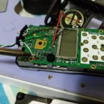
In my case the yellow jack is the input and the green is the output.
I wired the RX audio to the tip yellow contact, TX audio to the tip green contact and GND to the the first contact on the yellow or green.
You might need to choose the ring contact, for more information check page 18 on this PDF.
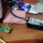
Later on I made a cable with jacks to easily connect it to the USB soundcard.
Connect PTT to GPIO 26 which is pin 37 and ground to ground (pin 39).
Now, let’s configure the software.
NOTE: don’t connect the USB soundcard via extension cable or USB hub.
I did use extension cable and it didn’t transmit.
First let’s check what’s the name of the soundcard on our system:
aplay –l
You’ll get a list of all the output devices on the RPi, look for this line:
card 1: Device [USB PnP Sound Device], device 0: USB Audio [USB Audio]
Subdevices: 0/1
Subdevice #0: subdevice #0
Before this line you should see many others as RPi have built in audio output but not input.
Check for the record device as well:
arecord -l
The output should look like this:
**** List of CAPTURE Hardware Devices ****
card 1: Device [USB PnP Sound Device], device 0: USB Audio [USB Audio]
Subdevices: 0/1
Subdevice #0: subdevice #0
Great!
Our RPi can recognize our input and output device.
Configuring Direwolf
Open the direwolf.conf file located in /home/pi
Scroll to until you see ADEVICE plughw:0,0And change the first 0 to the number you received on the last step, mine was card 1 so the line is:
ADEVICE plughw:1,0
Next, jump to CHANNEL 0 PROPERTIES
Edit MYCALL to meet you callsign (you can add SSID).
Find PTT and change it to GPIO -26
You might need to remove the minus as mine was inverted.
GPIO 26 is free on the RPi according to the pinout that can be found here.
Uncomment DIGIPEAT line under DIGIPEATER PROPERTIES
If you plan using it as iGate you can configure it under INTERNET GATEWAY section.
Change IGSERVER to the closest server to your location.
IGLOGIN is your callsign then password.
You can configure the beacons of the digipeater here.
If you want you can choose between RF and IG (Internet)
PBEACON sendto=0 delay=0:15 every=05:00 symbol="igate" via=WIDE1-1 power=4 gain=6 comment="Digipeater Test" overlay=T lat=14^4.55N long=52^54.12E
sendto=0 means channel 0 which is our RF, change to IG if you want to send it via the net.
delay=0:15 is the delay from the first time the software launches.
every=05:00 sets the time between beacons.
lat and lon sets your location.
All the rest is pretty self explanatory.
And we done.
Save the file and run direwolf again.
My system is still in test mode so I didn’t configure Direwolf to run on boot.
You can do it by creating service.
Read more here: https://www.raspberrypi.org/documentation/linux/usage/systemd.md
Or check page 28 on the PDF I linked to earlier.
You can do much more with Direwolf like connecting to its AGW or KISS ports, more info can be found on the user guide.
Audio level can be set with the command alsamixerPress F6 and choose the USB soundcard then move with the keyboard left and right to change the Mic or Speaker and up or down to change the levels.
When you done just hit ESC.
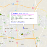
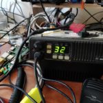
I called someone to help me test it and I was surprised to see that it worked:
![]()
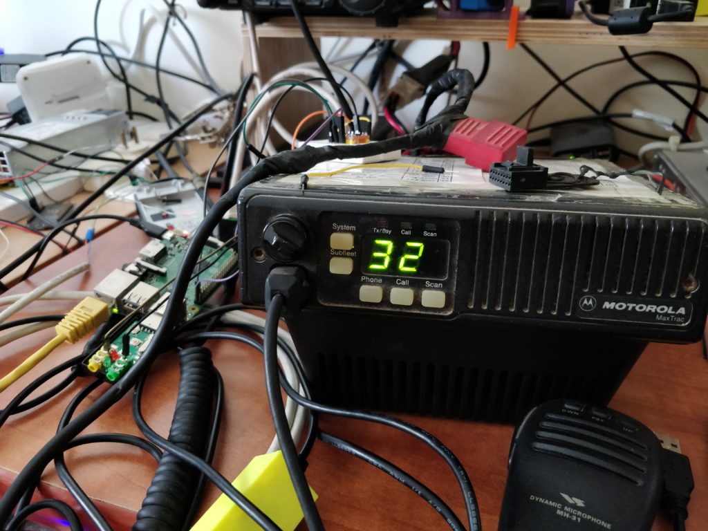
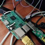
Maxtrac?
Since I had a Motorola Maxtrac sitting in my shack and collecting dust, I wanted to try and using it with my digpeater.
I programmed it to 144.800MHz (my local APRS frequency) and found the pinout for the 16 pin rear connection:
http://www.repeater-builder.com/motorola/maxtrac/maxtrac-option-plug.html
The pins are:
3 MIC PTT
5 FLAT TX AUDIO
7 Ground
11 RX AUDIO
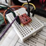
Please notice that the RPi is not 5V tolerant so you’ll have to use logic level converter for the PTT, I tried using voltage divider but it didn’t work.
I provided 3.3V from pin 1 and 5V from pin 2 on the RPi to power the HV and LV on the logic level converter.
The software alerted that the audio it too high but I didn’t try to fix it since it’s not going to be connected to the Maxtrac permanently.
That’s it.
You can find more information on the project documentation:
https://github.com/wb2osz/direwolf/tree/master/doc
And as usual, if you have any questions don’t hesitate to ask in the comments.
73!