DIY Magnetic Loop – Part 1 – The Capacitor
Introduction
Just a few months ago I moved to new QTH.
I started to look for places to hang a wire and work some HF but I couldn’t find any.
The balcony is too small and I can’t get access to the roof.
Placing a vertical antenna was also not possible as it’ll be in front of 2nd floor neighbors window.
Living in a city isn’t easy 🙂
I started searching for better solution and I found few types of antennas that can fill the gap.
In the end I settled on the Magnetic Loop, very narrow bandwidth antenna but that’s my only option right now.
If you’re not familiar with Magnetic Loop antennas, go read about it.
Those antennas are fascinating.
Here are two links that I had opened on my browser:
http://viennawireless.net/wp/wp-content/uploads/2017/01/Magnetic-Loop-Antennas-W4RAX.pdf
http://www.kk5jy.net/magloop/
A short explanation for the type of mag loop I wanted to build:
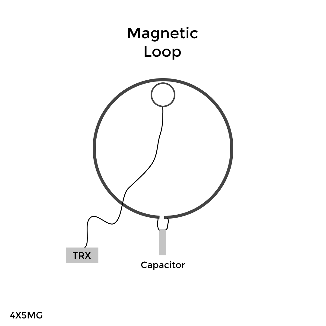
It’s made from few basic components:
- Main Loop
- Small Loop
- Capacitor
The small loop is wired to the radio with coax cable and coupled to the main loop which is connected to the capacitor.
My goal was to get an antenna for 40m-10m that can handle 100 Watts.
The Capacitor
As you probably know, there’s no perfect antenna and I had to give up on something.
The most expensive and hard to get component is the capacitor.
You need a variable capacitor to tune the antenna and you can choose between the popular types, vacuum capacitor and air gap one.
Vacuum cap have more Kv rating and usually more capacitance but it’s very expensive and it can’t be turned 360 degrees which is a downside if you want to tune it with motor later.
The cheaper option is air variable capacitor but if you want more capacitance you’ll need smaller plates, when you use smaller plates you need more plates to get to the maximum capacitance.
Another point to take in consideration is the spacing of the plates, you need more space for higher voltage rating but you loose capacitance.
That’s the reason I wanted to make my own capacitor.
I’ve used few websites to get the parameters I need for the cap.
https://www.changpuak.ch/electronics/Disc_Air_Capacitor_Calculator.php
http://www.66pacific.com/calculators/capacitor-calculator.aspx
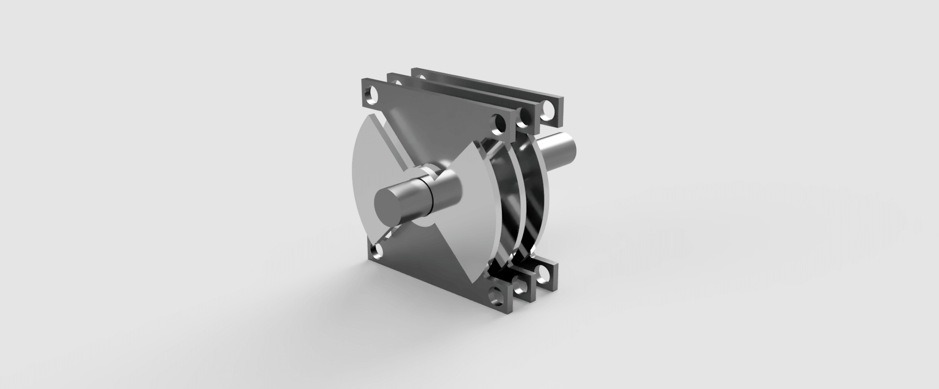
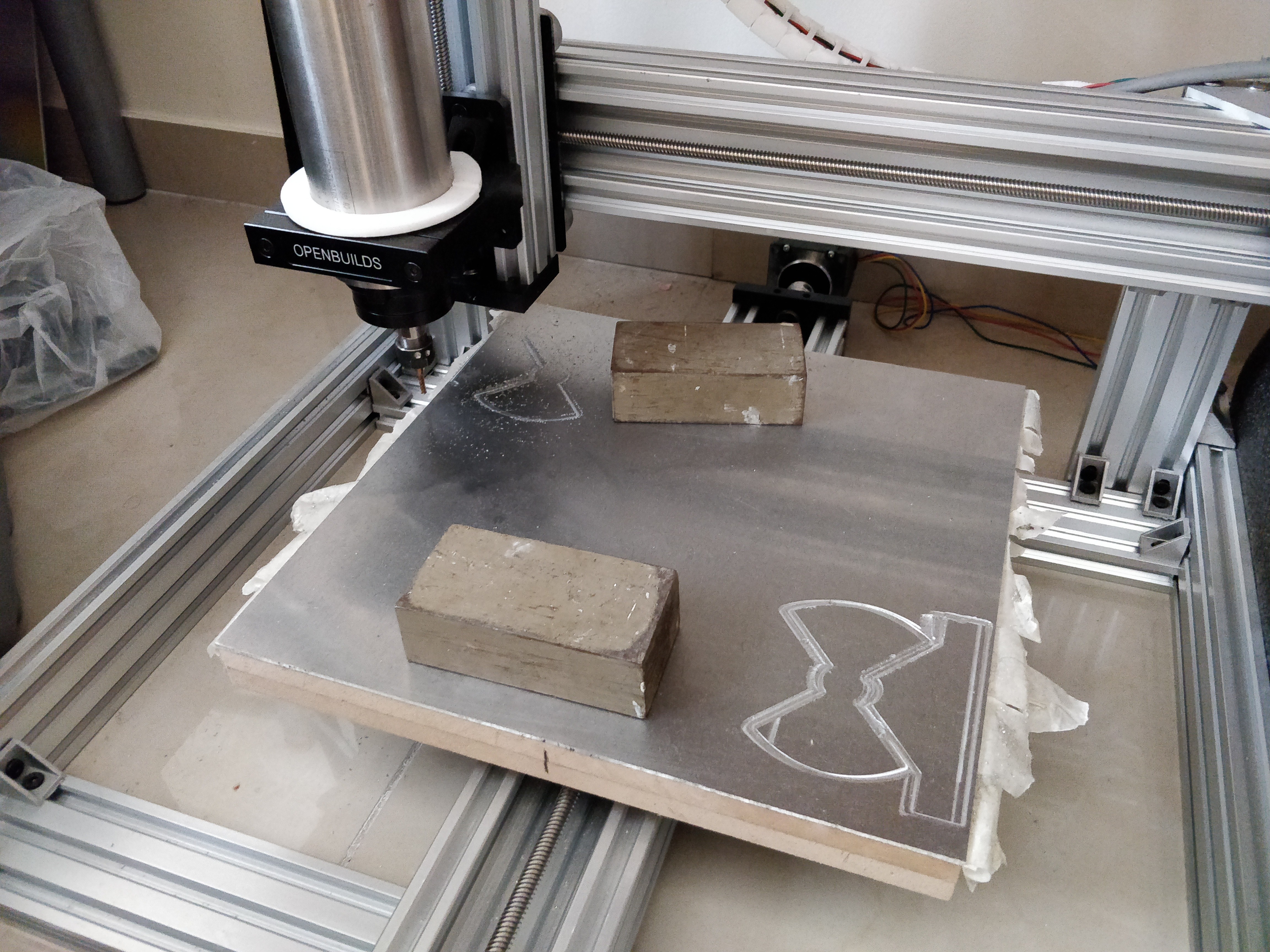
The design and model was made on Fusion360 as it has CAM processing inside and can output files for CNC machining.
I tried asking few people for cutting my plates but no one wanted to do small batch.
So I built a CNC machine 🙂
Bottom line, I couldn’t get it to work with aluminum (6061 2mm thick if you wonder).
I got too much chatter (vibrations) because I don’t have a way to clamp my aluminum sheet good enough.
Might need to buy smaller sheets.
As you can see, I tried cutting it but no luck.
I didn’t abandon this idea and I hope to do it again in the future.
Making my own capacitor can be very useful to design some other loops later.
And it’s fun experimenting with it.
I recommend checking out this series of posts about homemade capacitor and Magnetic Loop:
http://play.fallows.ca/wp/tools/cnc/butterfly-capacitor-plates/
After this nerve racking process (you always have the fear of something will explode or break) I moved to the next option, buying a kit.
I found few hams selling such a kit but one of them didn’t answer and the other charged for shipping unreasonable price.
In the end, I decided to go for pre-made capacitor.
To be continued…
73 for now!